Help
Bending analysis of the helical axis
| 1. Introduction |
| 2. Example |
| Close window |
Help |
Bending analysis of the helical axis
|
Regular nucleic acid double helix structures like the canonical A and B-helices are straight. Bending of a helix is always accompanied by irregularities or distortions of the helix geometry. Nevertheless, local distortions of helical parameters do not necessarily result in bending. Bending is a global property of a helix. A thorough analysis of helix geometry requires a global bending analysis as well as an analysis of local helical parameters.
In our bending analysis we use the helical axis as a reduced model of the helix. The curvilinear axis of the helix is calculated with CURVES. The bending analysis of the helical axis is performed by a numerical approach and by visualization. We use the term bending for any deviation of the helical axis from straightness. Furthermore, we distinguish several geometrical shapes of the helical axis, namely a straight line, a circular line (arc), a single-kink line and a double-kink line. It is obvious that there may be nucleic acid double helices that cannot be described by any of these models. We have found, however, by a comprehensive bending classification, that the ovewhelming majority of the currently known three-dimensional nucleic acid duplex structures with 6 or more consecutive base pairs can in fact be described by these models.

Figure 1. A nucleic acid double helix superimposed on its curvilinear axis. The orientation of the structure results from an alignment of the principle axis of inertia of the curvilinear axis with the coordinate axes of the viewing windows. The nucleic acid double helix is taken from PDB entry 2LEF.
In Figure 1 (obtained from the 'Analysis of nucleic acid double helix geometry' page) three orthogonal views of a nucleic acid double helix and its helical axis calculated with CURVES are shown. The structure is oriented in a special way. The coordinate axes of the viewing windows are the principle axes of inertia of the curvilinear axis. The moment of inertia is calculated using an equal mass for every point of the helical axis. The lowest principle moment of inertia is about the x-axis, the second lowest about the y-axis, and the highest about the z-axis. This assignment has some useful implications for the visualization of bending. The x-axis is identical to the straight line which would be obtained from a fit to the points of the helical axis. In Figure 2 (obtained from the 'Bending of the helical axis' page) the curvilinear axis is shown in the same orientation as in Figure 1. However, the duplex structure is omitted, and the principle axes of inertia are shown instead.
The views shown in Figures 1 and 2 allow for an immediate qualitative bending analysis. The helical axis shown in Figures 2 is not straight, but nevertheless nearly planar. The helical axis is bent in the side view 1where you look into the x-y plane, while it is straight in the side view 2 view. A planar helical axis deviates from the x-axis only in y-direction, but not in z-direction. A helical axis which shows significant deviations from the x-axis in the side view 1 as well as in the side view 2 is non-planar.
The images of the helical axis given on the 'Bending of the helical axis' page (Figure 2) can be modified interactively. The double helix can be superimposed on the helical axis, and the geometrical objects fitted to the helical axis can be switched off. The selection of geometrical objects is applied also to the 3-dimensional models. The 3-dimensional interactive models offer additional visual information which may not be obtained form the static images.
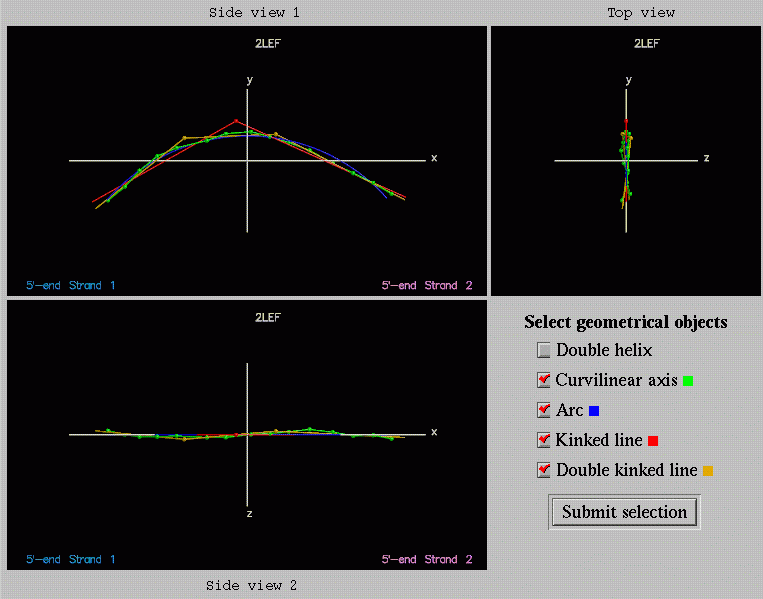
Figure 2. The curvilinear axis of a nucleic acid double helix and the geometrical objects fitted to the curvilinear axis. The axes of the viewing windows are the principle axes of inertia of the curvilinear axis.
The quantitative analysis of bending of the helical axis is done with the program ARC_FIT. The five simple geometrical objects listed in Table 1 are fitted to the helical axis. The simplex downhill algorithm is used for optimization. An object is only fitted if the number of points of the helical axis exceeds the number of independent parameters. The application restrictions we have used for each geometrical object are also given in Table 1.
When comparing the geometrical objects we must take into account the different numbers of independent parameters. The quantity sigma2 is the goodness of fit. It is calculated by normalizing the sum of square deviations (chi2) with the number of degrees of freedom. The number of degrees of freedom is the number of points of the helical axis diminished by the number of independent parameters of the geometrical object.
Table 1. The properties of the geometrical objects fitted to the helical axis.
| Model | Geometrical parameter | Planarity | Independent parameter |
Application restriction |
| Straight line | - | yes | 4 | at least 6 bp |
| Plane | - | yes | 3 | at least 6 bp |
| Circular line (arc) | radius of curvature r | yes | 6 | at least 7 bp |
| Single-kinkline | kink angle alpha lengths l1, l2 |
yes | 7 | at least 8 bp |
| Double-kink line | kink angles alpha1, alpha2 twist angles omega lengths l1, l2, l3 |
only if omega = 0°, 180° | 10 | at least 13 bp |
Some geometrical parameters can be derived from the models fitted to the helical axis (Table 1). The geometrical parameters are always provided, but only parameters derived from models which fit good are appropriate for characterizing the shape of the helical axis. The circular line (arc) yields the radius of curvature r. The single-kink and the double-kink lines give the lengths of straight axis segments and the kink angles. The definitions of these parameters are illustrated in Figures 3 and 4. The twist angle omega describes the torsion between the first and the third straight segment of the double-kinke line for rotation about the second segment. If omega is equal to 0° or 180°, the double-kinke line is planar. The length of a straight segment is defined by the number of points of the helical axis which are closest to that segment. The lengths are given in numbers of base pairs, since each point of the helical axis represents one base pair. Due to this choice it is rather easy to localize the kink points with respect to the base pair sequence.

Figure 3. Parameters derived from a kinked line. s1, s2: straight segments; alpha: kink angle defined as deviation from straightness; n0: normal vector of the plane spanned by s1 and s2.
A special case of the double-kinke line arises if the central segment is assigned to less than two points of the helical axis. The two nearby kink points indicate a displacement between two straight segments of the helical axis. In this case the kink angles of the double kinked line are not meaningful, but the first and the third segment of the double kinked line can be interpreted as two skewed lines. This type of bending is found with purine repressor/DNA complexes (for example PDB code 2PUE).
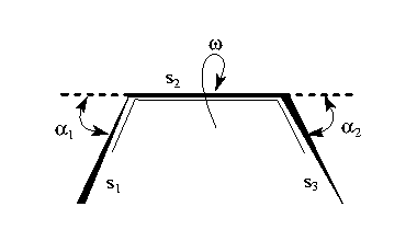
Figure 4. Parameters derived from a double kinked line. s1, s2, s3: straight segments; alpha1, alpha2: kink angles defined as deviation from straightness; omega: torsion angle between segments s1 and s3 for rotation about s2.
Bending of the helical axis can be classified as planar or non-planar (Figure 5). The geometrical objects used by ARC_FIT can approximately describe the shape of the helical axis in several cases. Nevertheless, there may be other cases (planar or non-planar) where the shape is more complex and none of these geometrical objects is adequate.
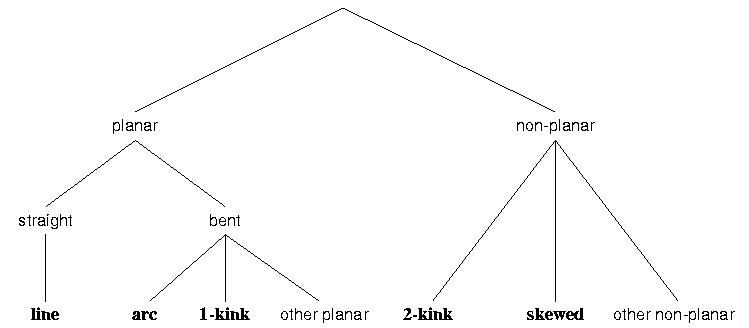
Figure 5. Classification of the geometrical objects with respect to their planarity. The geometrical objects employed in the program ARC_FIT are given in bold (1-kink: kinked line, 2-kink: double kinked line). Skewed lines are a special case of the double kinked line where the first and the third segment are interpreted as two skewed lines.
Here we discuss the results of the bending analysis for PDB entry 2LEF in more detail. This structure is a protein/DNA complex with a 15 bp DNA double helix bound to the DNA binding domain of the transcription factor LEF1. The DNA binding domain is a high mobility group (HMG) domain. In this case the protein binds as a monomer to the minor groove of the DNA. The DNA is bent away from the protein. The structure was solved in solution by NMR.
The orthogonal views resulting from the bending analysis are shown in Figure 2. The green points represent the curvilinear helical axis calculated with CURVES. From the front and top views one can immediately see that the helical axis is bent and also planar. None of the three models (arc, kinked line, double kinked line) fit very well. However, the kinked line is the least appropriate one. This means that the mode of bending is complex and cannot be described by a single sharp kink. Upon closer inspection it turns out that the left part is better fitted by the arc, while the double kinked line represents the right part rather well. Thus, the shape of the helical axis can be described as a combination of a smoothly bent segment (left side) with a straight segment (right side).
Table 2. Bending parameters of the nucleic acid double helix from 2LEF, determined with the program ARC_FIT.
| Model | sigma2 / Å2 | Geometrical parameters |
| Plane | 0.169 | |
| Straight line (x-axis) | 13.240 | |
| Arc | 0.590 | Radius of curvature: r = 26 Å |
| Kinked line | 0.854 | King angle: alpha = 54° Lengths of straight segments: l1 = 7 bp, l2 = 8 bp |
| Double kinked line | 0.407 | King angles: alpha1 = 37°, alpha2 = 30°
Twist angle: omega = -28° Lengths of straight segments: l1 = 5 bp, l2 = 4 bp, l3 = 6 bp |
The bending parameters listed in Table 2 are in line with the conclusions drawn from the visual examination. A rather high value of sigma2 = 13.240 Å2 places the straight line out of any discussion, while the low value of sigma2 for the plane indicates that the axis is nearly planar. The kinked line is also not adequate here because the value of sigma2 is significantly higher than for the arc and the double kinked line. Overall, the double kinked line fits better than the arc. The lengths of the straight segments are 5 bp, 4 bp, and 6 bp. Thus the two kink points are located next to the center of the helical axis, 4 bp apart from each other. However, the orthogonal views and also the 3-dimensional models show, that there are not really two sharp kinks in the central part of the helical axis. A combination of an arc and a straight segment would be the best model for this axis. Currently, such a model is not included in out analysis tool. This example shows that visual inspection and numerical results have to be used hand in hand in order to understand the complex 3-dimensional shape of a helical axis.
| Perl script: | help.pl (22 Mar 1999) |
| Author: | Peter Slickers and Jürgen Sühnel (slickers@imb-jena.de, jsuehnel@imb-jena.de) IMB Jena, Germany |